Design Module

Expand the CAD Functionality and Import CAD Files into COMSOL Multiphysics® with the Design Module

 Read more below 

Want to know more?

I Want To Know More Form

Create Your Own Designs

Constraints and Dimensions

The Design Module includes a set of sketching tools used for adding constraints and dimensions to planar drawings for 2D models, 3D work planes, and in geometry parts. The constraint options include parallel, perpendicular, and tangent constraints. For example, to make two polygon segments meet at 90 degrees, you click on the two edges and use a perpendicular constraint. The options for dimensions include length dimension, radius, and angle. You can, for example, simply click and drag an edge to interactively set a length dimension. To aid in creating consistent drawings, the Design Module gives you immediate feedback, whether a sketch is underdefined, overdefined, or well defined.
Parametric Designs

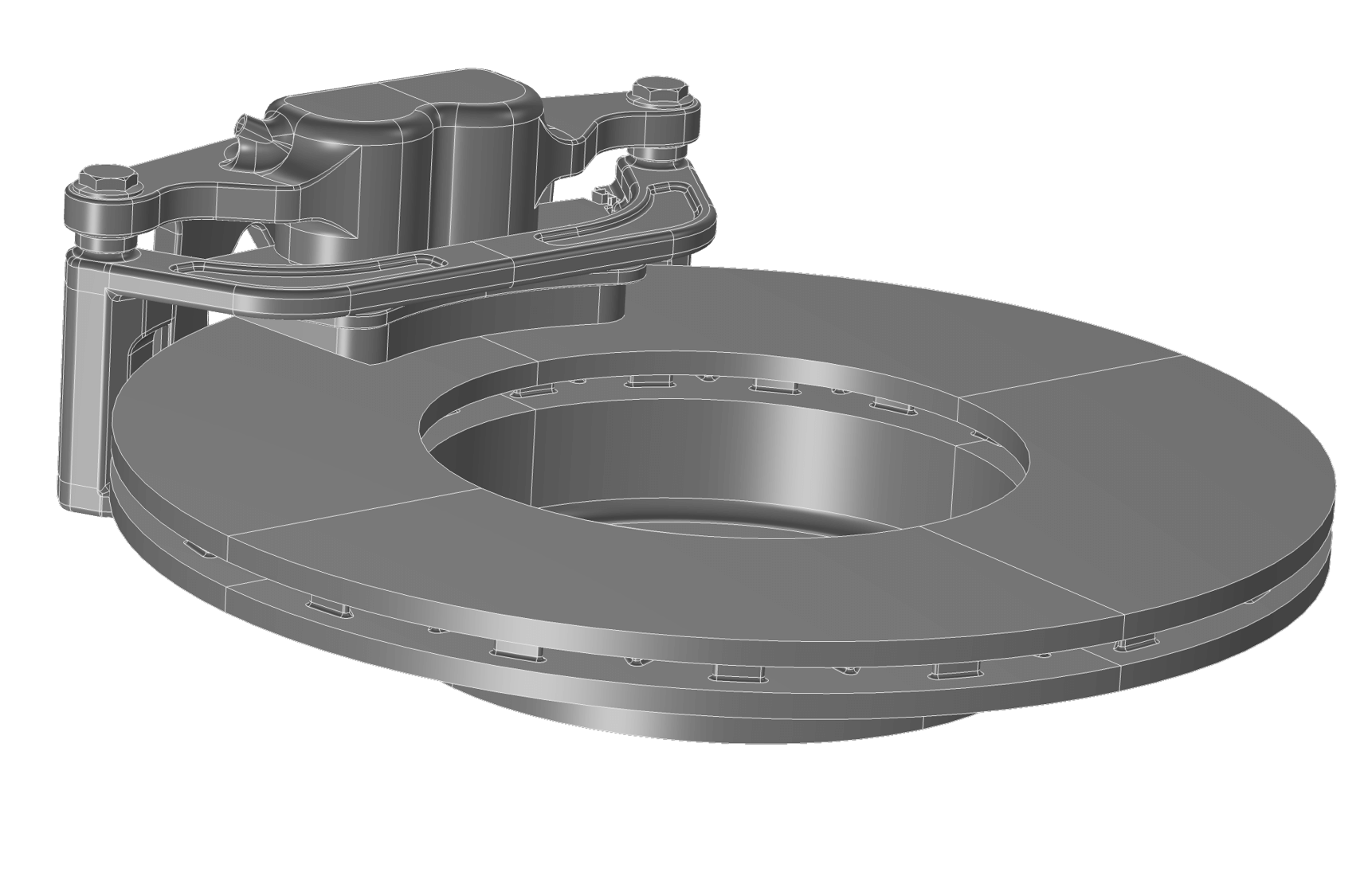
All of the dimensions detailed above can be made parametric using the general parametric framework in COMSOL Multiphysics®. This enables you to run parametric sweeps across one, or multiple, dimensions. Additionally, when combined with the Optimisation Module, you can run parametric optimisations, taking full advantage of the parametric functionality.

Fillet, Chamfer, Loft, Thicken, Midsurface, and Advanced Boolean Operations

The Design Module gives you access to standard CAD operations, such as fillet, chamfer, loft, thicken, and midsurface, as well as more advanced Boolean operations.
Fillet

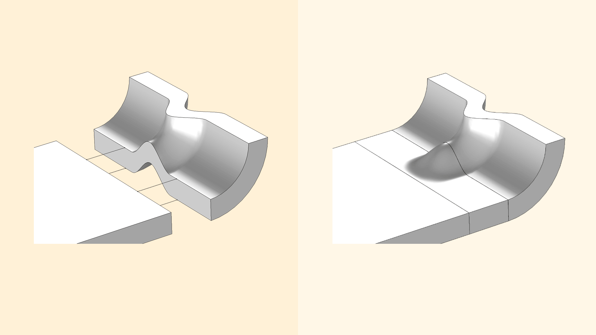
Fillets are created by simply clicking on an edge and specifying a radius. This will create rounded corners on the selected set of edges and is used, for example, in structural mechanics to avoid stress concentrations and in electromagnetics to avoid electric breakdown.

Chamfer

Chamfers are created by simply clicking on an edge and specifying a distance. This will create beveled corners at the selected edges.

Loft

The Loft operation lets you specify a set of profile curves. The output of this operation is a loft surface, which consists of one or several faces that interpolate the profiles. This operation is used to create smooth geometric transitions between profile curves of different shapes.

Thicken

The Thicken operation is used to convert a surface object to a solid object by giving it a thickness, usually in the normal direction.

Midsurface

The Midsurface operation removes the thickness of a solid object having constant thickness, resulting in a surface object. Such surface objects are typically used with a Shell interface where the thickness is represented as a physics property instead of a geometric feature.

Advanced Boolean Operations

The Design Module provides more advanced Boolean operations that are expected to yield better results for more complex geometry models, for example, when computing the union of objects having touching faces that do not match exactly.
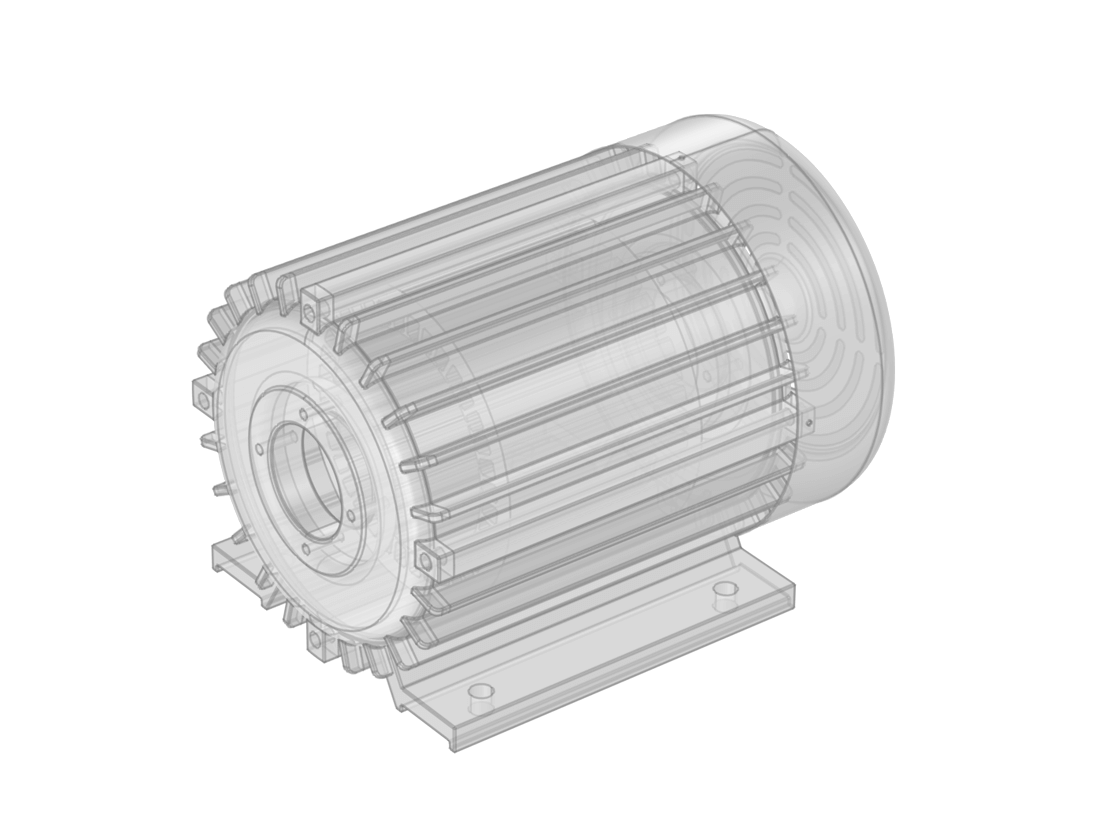
Importing and Augmenting CAD Models

Import and Export Your Models from and to CAD Software
Repairing the Geometry Manually or Automatically
Defeaturing Models to Augment Better Meshing and Simulations
Virtual Operations Concentrate Simulations to Regions that Matter
Associative CAD Import
Supported Formats for File Import/Export
Interfacing Directly with CAD Software
The Design Module supports the import of a wide range of common file formats, including the Parasolid® software, ACIS® software, STEP, and IGES formats. Moreover, you can import the native file formats of a number of CAD tools, such as the SOLIDWORKS® software, Inventor® software, AutoCAD® software, PTC® Creo® Parametric™ software, NX™ software, and CATIA® V5 software (requires a separate add-on product).

Imported CAD files are automatically converted to the format of the Parasolid® 3D geometric modelling engine within the Design Module. You can then modify and manipulate them using the Fillet, Chamfer, Loft, Thicken, and Midsurface operations, for example. Additionally, you can encapsulate geometries to model phenomena in the surrounding domains. After changes to a geometry have been made, you can export them in the Parasolid®, ACIS®, STEP, IGES, or STL file formats for import into other tools.
You can always perform geometry repair when importing a CAD design into the Design Module — even by default.

Geometry repair ensures the validity of the imported geometric information to avoid problems with meshing the geometry. Several types of problems are checked for and fixed during import, including tolerance issues that would prevent a perfect connection of geometric entities, self-intersecting entities, and very small edges and sliver faces.

The Design Module also contains tools to detect problems and repair selected CAD models to a specified tolerance. This way, you can adjust the tolerance to knit imported surfaces in order to generate a solid, or to remove small geometric entities, without the need to reimport the CAD file.
A sound geometry can still contain geometric features that make it difficult to mesh or perform an efficient simulation. In particular, small features may concentrate large numbers of mesh elements in regions where changes in the simulation results are negligible and can thus be ignored.

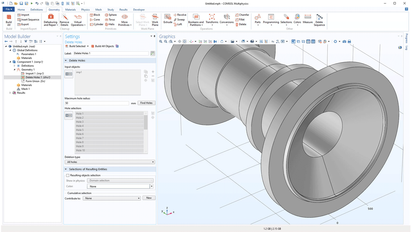
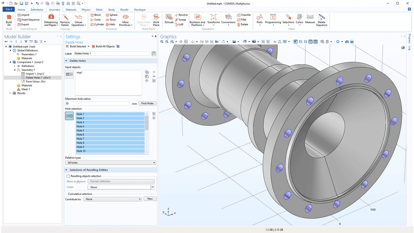
The Design Module contains tools for defeaturing by identifying and removing certain features, such as spikes, holes, slivers, short edges, and small faces, for example. Other defeaturing tools allow you to fill in grooves, cap faces, and remove fillets.

Using the Design Module, you can reintroduce deleted features, such as fillets and holes, and run a parametric sweep to study their influence on the simulation.
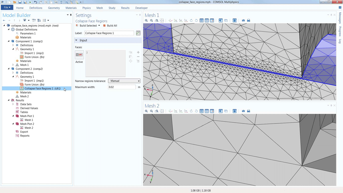
Virtual geometry operations are a useful tool within COMSOL Multiphysics® that provides better meshing analysis solutions. This is done through instructing your meshing tool to ignore selected entities and features, thereby avoiding concentrating meshing in these regions — the meshing is taking place on a virtual geometry.

The ignored regions would typically be part of the geometry where your simulation results are uniform or irrelevant to your particular situation. You can use virtual geometry operations to ignore edges, vertices, and faces; subsequently form composite objects; or collapse the entities.

The automatic Remove Details operation analyses the geometry and applies a sequence of virtual geometry operations in order to ignore undesirable features in the model.

These operations are included in COMSOL Multiphysics®, and complement the geometry manipulation capabilities of the Design Module, particularly when certain features are difficult or undesirable to remove through the Design Module repair and defeaturing tools.
The Design Module import functionality supports associative geometry import to retain physics and other settings on the geometry. Once a file has been imported, the software reads information in the CAD files to identify the geometric entities in the file. If and when the file is reimported due to a design change, all of the selections in COMSOL Multiphysics® will be updated and retained according to associativity rules, eliminating duplicate work. This information is usually available when importing CAD files saved in the native format of the software where it was created.
Supported Formats for File Import

The following table lists the file formats included with the Design Module; for all supported file formats, see the file formats page. Note that not all file formats are supported on all operating systems; for details, see the system requirements.

File Format
Extension
Version
Import
Export
All trademarks listed herein are the property of their respective owners, and COMSOL AB and its subsidiaries and products are not affiliated with, endorsed by, sponsored by, or supported by those trademark owners. For a list of such trademark owners, see http://www.comsol.com/tm.

If you are a CAD user who is looking for a CAE tool, the LiveLink™ products from COMSOL for leading CAD software provide additional functionality to connect your CAD system directly with COMSOL Multiphysics®. The synchronisation feature in the LiveLink™ products automatically updates the geometry in one program when changes are made in the other. With the LiveLink™ products, you avoid the import/export and reimporting of the entire CAD geometry when you want to make changes for further analysis. Additionally, parametric sweeps can automatically be run based on a geometric parameter such as the length of an edge, and you can even run analyses to optimise the CAD geometry based on the simulation results.

The list of current products that contain this functionality are as follows:

Every business and every simulation need is different.

In order to fully evaluate whether or not the COMSOL Multiphysics® software will meet your requirements, you need to contact us. By talking to one of our sales representatives, you will get personalised recommendations and fully documented examples to help you get the most out of your evaluation and guide you to choose the best license option to suit your needs.

Fill in your contact details and any specific comments or questions, and submit. You will receive a response from a sales representative within one business day.

Request a Software Demonstration:
Request Software Demonstration

Want to know more?

I Want To Know More Form
(COMSOL®, COMSOL Multiphysics®, Capture the Concept, COMSOL Desktop®) are registered trademarks of COMSOL AB, LiveLink™ is an unregistered trademark of COMSOL AB, ACIS and SAT are registered trademarks of Spatial Corporation. AutoCAD, AutoCAD Inventor and Inventor are registered trademarks or trademarks of Autodesk, Inc., and/or its subsidiaries and/or affiliates in the USA and/or other countries. CATIA is a registered trademark of Dassault Systèmes or its subsidiaries in the US and/or other countries. Microsoft, Excel and Windows are registered trademarks or trademarks of Microsoft Corporation in the United States and/or other countries. Parasolid and Solid Edge are trademarks or registered trademarks of Siemens Product Lifecycle Management Software Inc. or its subsidiaries in the United States and in other countries. SolidWorks is a registered trademark of Dassault Systèmes SolidWorks Corporation. Creo and Pro/ENGINEER are trademarks or registered trademarks of PTC Inc. or its subsidiaries in the U.S. and in other countries. MATLAB is a registered trademark of The MathWorks, Inc. Amazon Web Services, the “Powered by Amazon Web Services” logo, Amazon EC2 and Amazon Elastic Compute Cloud are trademarks of Amazon.com, Inc. or its affiliates in the United States and/or other countries. Mac and Macintosh are trademarks of Apple Inc., registered in the U.S. and other countries. Linux is a registered trademark of Linus Torvalds. Red Hat is a registered trademark of Red Hat, Inc. in the U.S. and other countries. Neither COMSOL nor any COMSOL products are affiliated with, endorsed by, sponsored by, or supported by any of these other trademark owners. Other product names, brand names or logos are trademarks or registered trademarks of their respective holders.
chevron-left-circlechevron-right-circle