CAD Import Module

Import CAD Files into COMSOL Multiphysics® with the CAD Import Module

 Read more below 

Want to know more?

I Want To Know More Form

Importing CAD Files

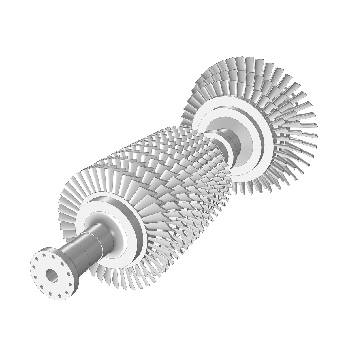
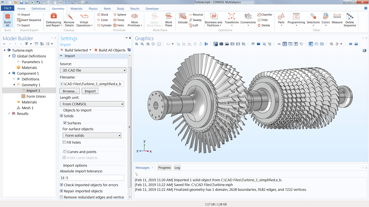
All CAD software supports the export of Parasolid®, ACIS®, STEP, and IGES file formats, which can then be readily imported into COMSOL Multiphysics®. In addition, the CAD Import Module allows you to import the native file formats of a number of CAD systems, such as SOLIDWORKS®, Inventor®, PTC® Creo® Parametric™, NX™, and AutoCAD®. The separate File Import for CATIA® V5 provides support for importing the native file format for this system. When you have installed the CAD Import Module, all CAD files are automatically converted to a Parasolid® geometry using the Parasolid® geometry engine that is included with the module. These geometries can subsequently be changed by the tools within COMSOL Multiphysics® and the CAD Import Module, including, for instance, a conscious change to the geometry. An example of this is creating a model domain around a CAD design, such as an enclosure for use in, for example, a CFD, acoustics, or electromagnetics analysis. Most CAD models are geometries of the objects to be manufactured, and simulation may be used to model the phenomena around this object, such as the flow of air. When these changes have been made, the CAD Import Module can export them in the IGES, STEP, Parasolid® or ACIS® file formats for import into other tools.

Supported Formats for File Import

Note that not all file formats are supported on all operating systems; for details, see the system requirements.

File Format
Extension
Version
Import
Export

Processing Geometry for Analysis

When running a finite element analysis, cleaning up the geometry for the analysis is just as important as importing the geometry itself. The CAD Import Module contains the necessary tools for repairing geometry that inherits errors upon transfer, defeaturing geometry that is overly detailed, and removing geometric entities that cause unnecessarily fine meshes.
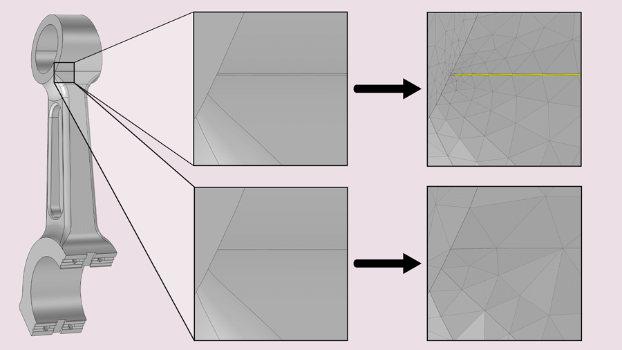
Repair a Geometry on Import
Defeature a Geometry for Analysis
Perform Virtual Geometry Operations to Simplify Mesh
Interfacing Directly with CAD Software
The goal of building the CAD model is to obtain a digital representation of the real product. This digital version contains the 3D geometry of the product together with the information needed for manufacturing it. While a 3D CAD geometry is usually true to the real object it represents, small and hardly noticeable anomalies can occur throughout the geometry. This may be due to numerical limitations in the computer's ability to represent complex shapes, limitations of some older CAD file format, human errors, or translation of the data between file formats. These small anomalies may result in, for example, faces that do not meet exactly at the edges or inconsistent face normals and edge directions. In turn, this may lead to problems with forming valid, watertight geometric objects when generating a mesh within COMSOL Multiphysics®. Therefore, geometry repair is always performed by default during the import process to get you started with your simulations.
In addition to the automatic repair that occurs on import, the CAD Import Module provides features that allow you to manually repair your CAD models after import. You can, for example, manually select faces and knit them together to form a solid using a specified tolerance to close gaps. Alternatively, you can automatically locate the edges of gaps and use these edges as input to generate a new face that covers the gap and forms a solid.
Once the CAD model has been properly repaired, it may still be difficult to use in a simulation due to the complexities of the geometry and the number of small geometric features in the model. If not removed from the geometry before meshing, these features may lead to an overly inflated number of mesh elements, and therefore, require more computational resources than necessary.

While some features, such as fillets, grooves, threads, and holes, are required for an eventual manufacture, they may not always be relevant to an overall simulation of the CAD model. The CAD Import Module has the tools to remove them and simplify the geometry. You can delete fillets and chamfers; fill holes; and delete groups of faces, replacing them with a uniform surface through filling or patching.

Other unwanted features may have resulted from the CAD modelling and import process itself, like small faces, sliver faces, spikes, and short edges, for instance. For these unintentional features, you can select their type in an interface and specify a tolerance value to identify and remove all occurrences of this geometric feature. Defeaturing can also be performed automatically as part of the import process, utilising the same tolerances specified for repairing.
Performing virtual geometry operations is similar to the defeaturing process, except that the imported geometry remains unchanged. Instead of changing the geometry, the virtual geometry operations instruct the mesher to ignore certain features that either do not influence the simulation greatly or are not particularly relevant to the desired simulation. The meshing subsequently takes place on a virtual geometry. Such operations involve ignoring vertices, edges, and faces; forming composite edges and faces; collapsing edges and faces; and more.

There are two ways to employ virtual geometry operations. The faces, edges, and vertices to be ignored can be manually selected, but there is also an automatic Remove Details operation to automatically recognise and remove small features by using a sequence of virtual operations (which can then be edited as necessary).

These operations are included in the base package, COMSOL Multiphysics®, and are a great complement to the defeaturing tools of the CAD Import Module. This functionality is particularly useful when the features of the geometry cannot be easily removed through defeaturing or repair, or when the simulation requires you to keep the curvature of the geometry intact.
You can choose from a large material database that includes:

The CAD Import Module provides tools to ensure a smooth transition of a geometry from a CAD software to your COMSOL Multiphysics® analysis, which is perfect for a CAE engineer who does not have access to the CAD program. If you are a CAD user who is looking for a CAE tool, the LiveLink™ products from COMSOL provide additional functionality to connect your CAD system directly with COMSOL Multiphysics®. The synchronisation feature in the LiveLink™ products automatically updates the geometry in one program when changes are made in the other. With the LiveLink™ products, you avoid the import/export and reimporting of the entire CAD geometry when you want to make changes for further analysis. Additionally, parametric sweeps can automatically be run based on a geometric entity such as the length of an edge, and you can even run analyses to optimise the CAD geometry based on result parameters.

The list of current products that contain this functionality are as follows:


All trademarks listed herein are the property of their respective owners, and COMSOL AB and its subsidiaries and products are not affiliated with, endorsed by, sponsored by, or supported by those trademark owners. For a list of such trademark owners, see http://www.comsol.com/tm.
Every business and every simulation need is different.

In order to fully evaluate whether or not the COMSOL Multiphysics® software will meet your requirements, you need to contact us. By talking to one of our sales representatives, you will get personalised recommendations and fully documented examples to help you get the most out of your evaluation and guide you to choose the best license option to suit your needs.

Fill in your contact details and any specific comments or questions, and submit. You will receive a response from a sales representative within one business day.

Request a Software Demonstration:
Request Software Demonstration

Want to know more?

I Want To Know More Form
(COMSOL®, COMSOL Multiphysics®, Capture the Concept, COMSOL Desktop®) are registered trademarks of COMSOL AB, LiveLink™ is an unregistered trademark of COMSOL AB, ACIS and SAT are registered trademarks of Spatial Corporation. AutoCAD, AutoCAD Inventor and Inventor are registered trademarks or trademarks of Autodesk, Inc., and/or its subsidiaries and/or affiliates in the USA and/or other countries. CATIA is a registered trademark of Dassault Systèmes or its subsidiaries in the US and/or other countries. Microsoft, Excel and Windows are registered trademarks or trademarks of Microsoft Corporation in the United States and/or other countries. Parasolid and Solid Edge are trademarks or registered trademarks of Siemens Product Lifecycle Management Software Inc. or its subsidiaries in the United States and in other countries. SolidWorks is a registered trademark of Dassault Systèmes SolidWorks Corporation. Creo and Pro/ENGINEER are trademarks or registered trademarks of PTC Inc. or its subsidiaries in the U.S. and in other countries. MATLAB is a registered trademark of The MathWorks, Inc. Amazon Web Services, the “Powered by Amazon Web Services” logo, Amazon EC2 and Amazon Elastic Compute Cloud are trademarks of Amazon.com, Inc. or its affiliates in the United States and/or other countries. Mac and Macintosh are trademarks of Apple Inc., registered in the U.S. and other countries. Linux is a registered trademark of Linus Torvalds. Red Hat is a registered trademark of Red Hat, Inc. in the U.S. and other countries. Neither COMSOL nor any COMSOL products are affiliated with, endorsed by, sponsored by, or supported by any of these other trademark owners. Other product names, brand names or logos are trademarks or registered trademarks of their respective holders.
chevron-left-circlechevron-right-circle