Ray Optics Module

Simulate Ray Tracing in Optically Large Systems with the Ray Optics Module

 Read more below 

Want to know more?

I Want To Know More Form

Optical Ray Tracing Software

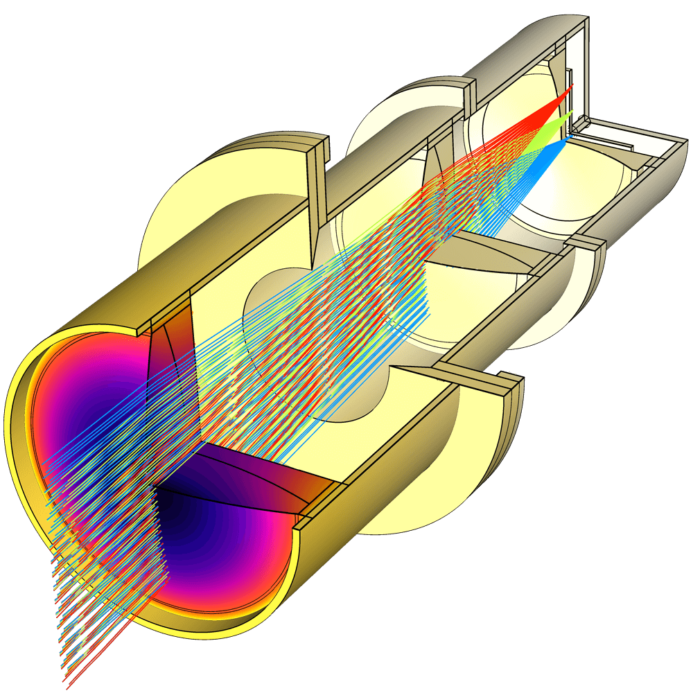
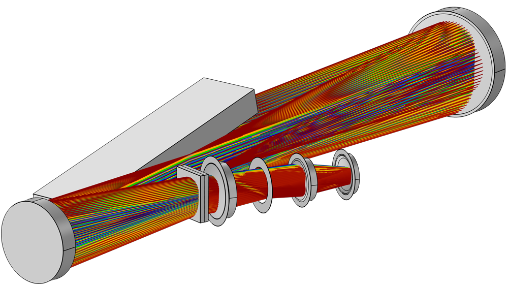
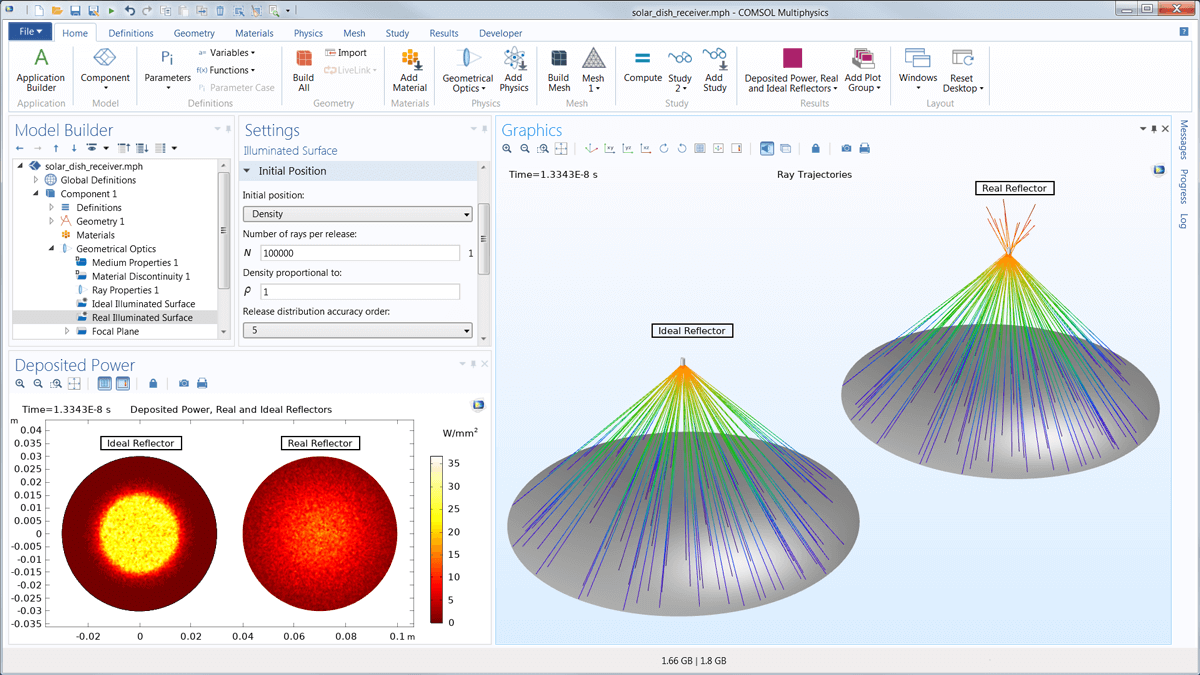
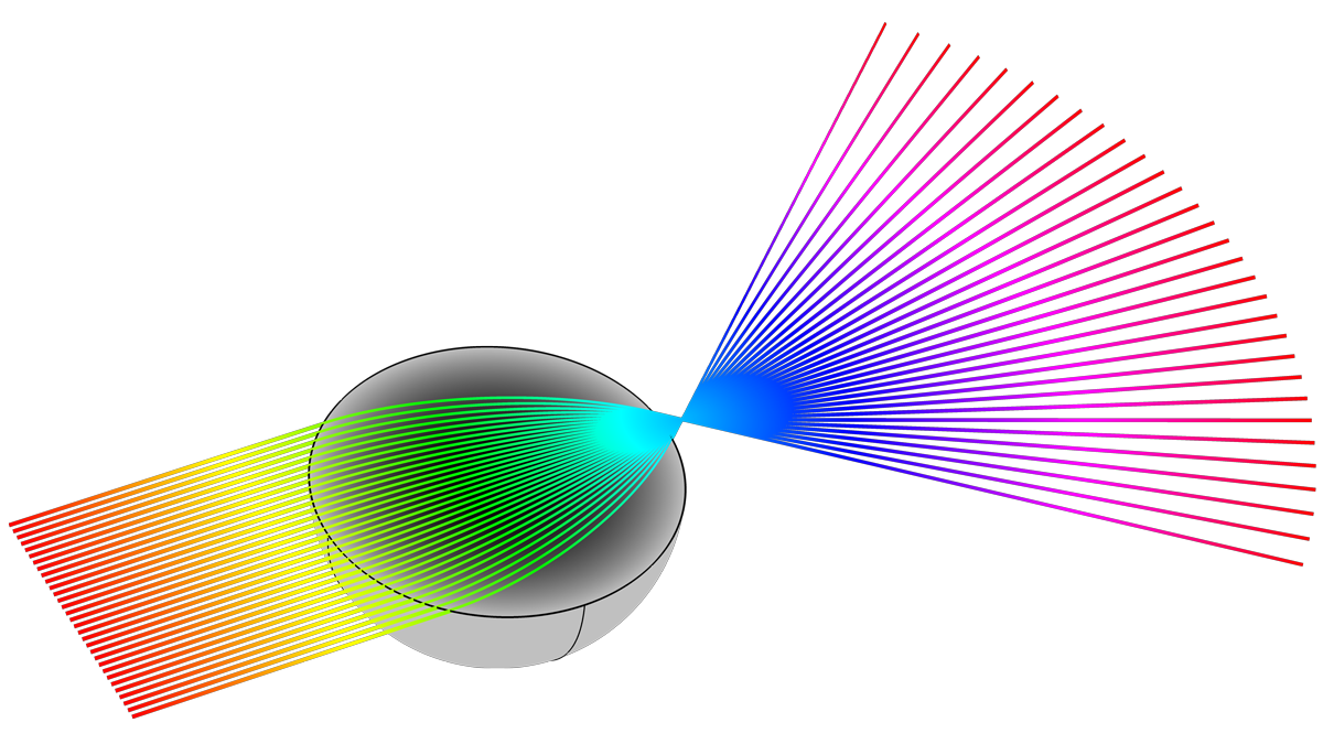
The Ray Optics Module is an add-on to the COMSOL Multiphysics® software that allows you to model electromagnetic wave propagation with a ray tracing approach. The propagating waves are treated as rays that can be reflected, refracted, or absorbed at boundaries in the model geometry. This treatment of electromagnetic radiation uses approximations that are appropriate when the geometry is large compared to the wavelength.

Combining the Ray Optics Module with other modules from the COMSOL® product suite enables ray tracing in temperature gradients and deformed geometries, allowing for high-fidelity structural-thermal-optical performance (STOP) analysis within a single simulation environment.

What You Get with the Ray Optics Module

The Ray Optics Module provides tools for specialised ray optics modelling when combined with the core functionality of the COMSOL Multiphysics® software platform.

The Ray Optics Module includes tools for modeling:
  • Automotive lighting
  • Building and room lighting
  • Cameras
  • Graded-index (GRIN) lenses
  • Interferometers
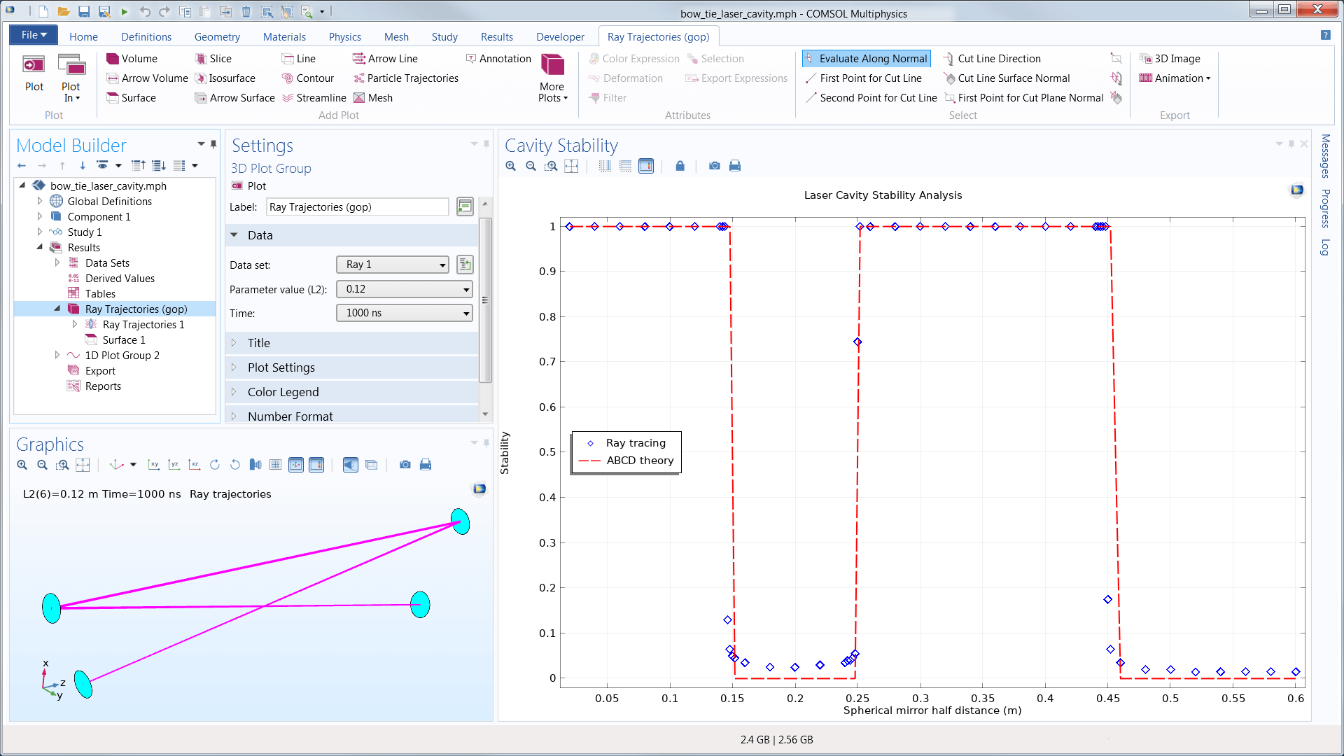
  • Laser cavity stability analysis
  • Laser focusing systems
  • Lidar systems
  • Optical filters
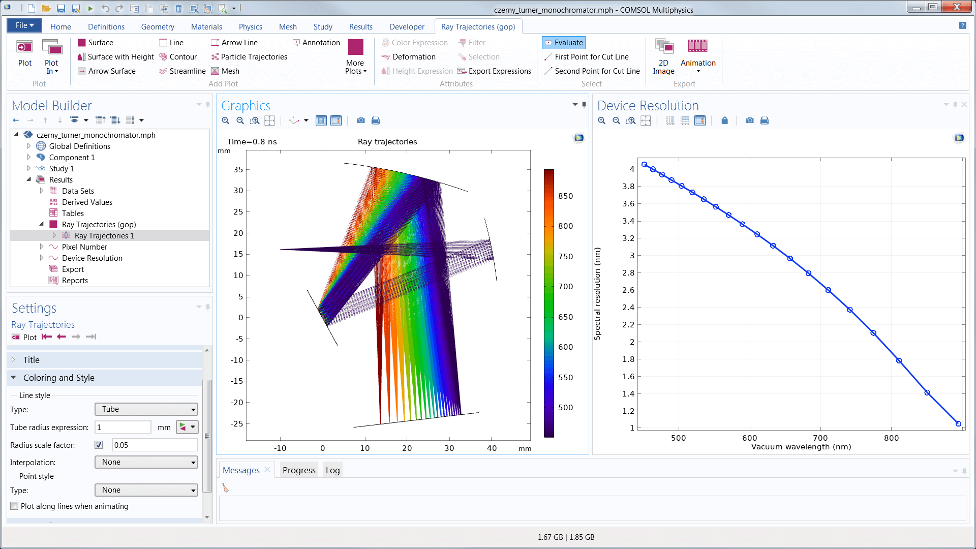
  • Monochromators
  • Solar radiation and solar energy harvesting
  • Spectrometers
  • Structural-thermal-optical performance (STOP) analysis
  • Telescopes
  • Thermal lensing
Multiphysics couplings:

Included with the Ray Optics Module:

  • Ray heat source

Ray Optics Module Features and Functionality

Explore the features and functionality of the Ray Optics Module in more detail by expanding the sections below.
Geometry Creation: Easy Setup of Lens and Mirror Geometries
Material Properties: Optical and Thermo-Optic Dispersion Models
Boundary Conditions: Versatile and Intuitive Features
Ray Release: A Variety of Mechanisms
Numerical Method and Study: A Robust, Flexible Ray Tracing Algorithm
Postprocessing Tools: Visualising Ray Paths
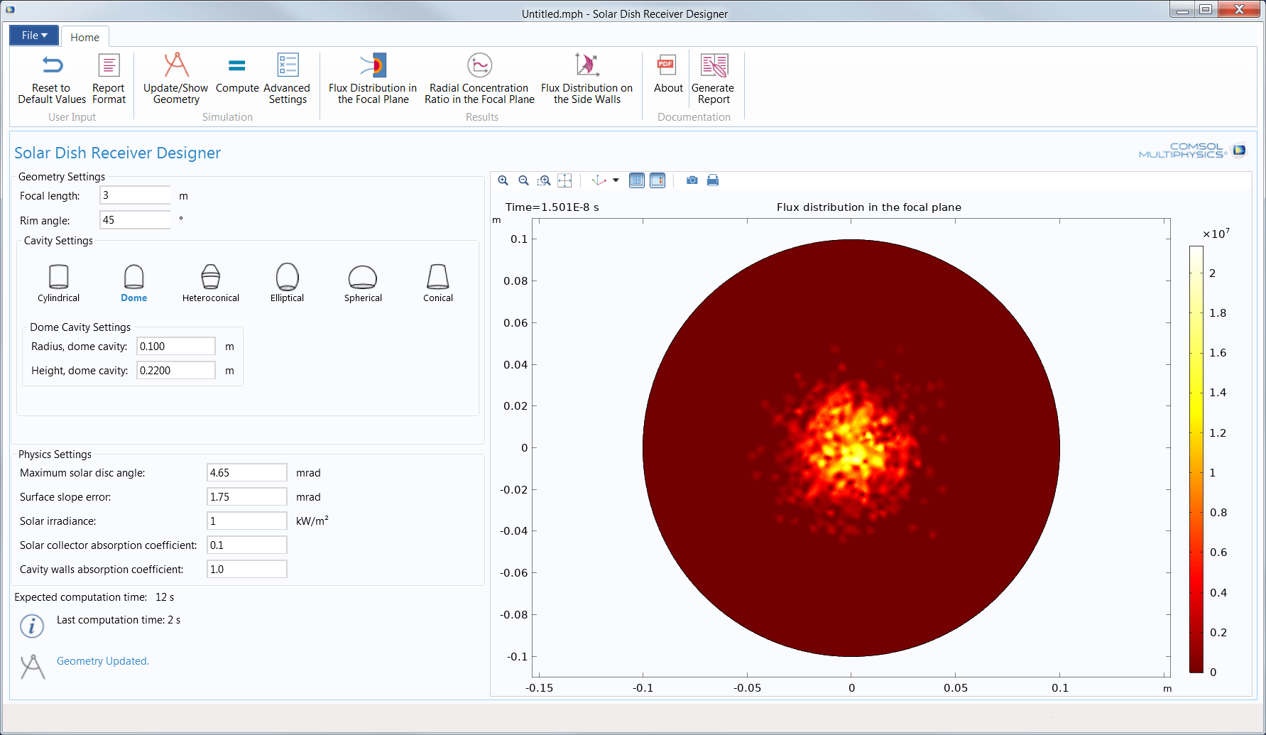
Simulation Applications: Customise Your Model Inputs and Outputs
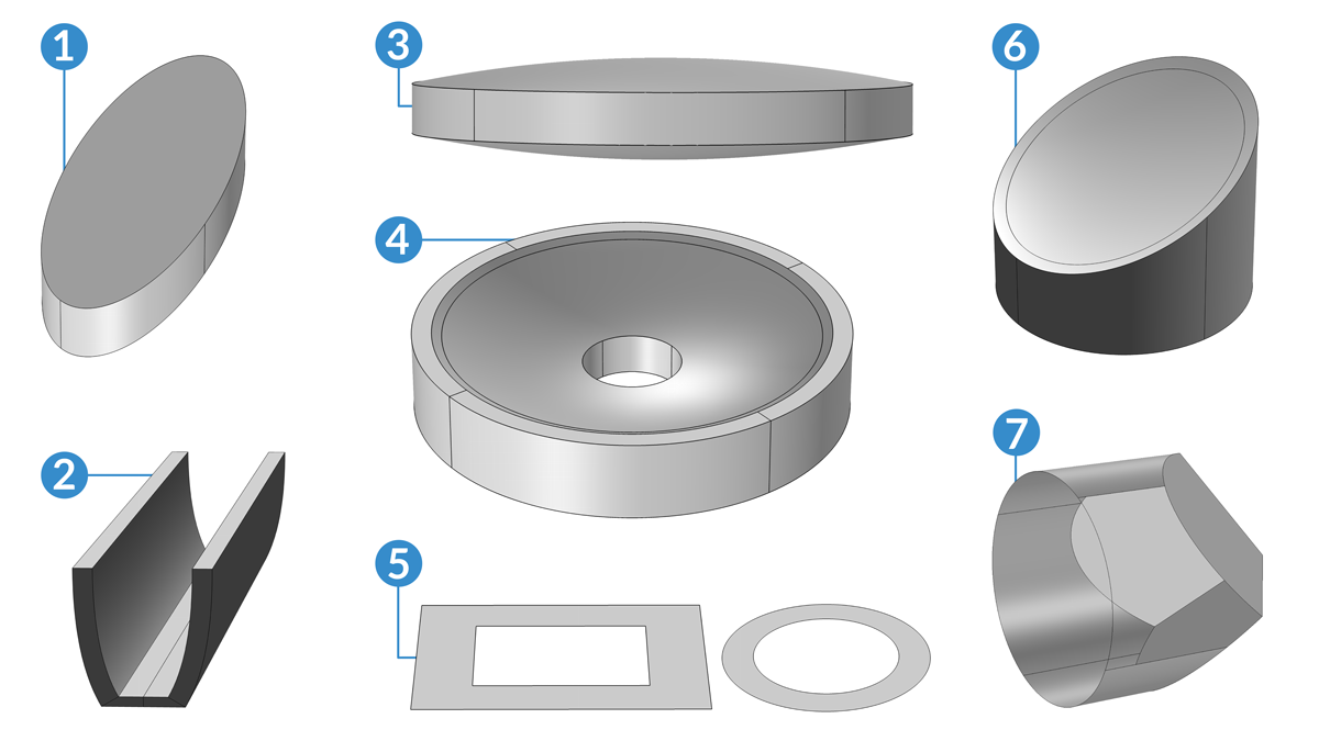
The Ray Optics Module includes a library of essential geometry parts, including mirrors, lenses, prisms, and aperture stops. Each of these parts is fully parameterized, and many of them include variants with different combinations of input parameters so they can be conveniently modified to fit an optical design.

For example, you can insert a spherical or conic mirror into the geometry sequence; specify whether the surface is concave or convex; enter its radius of curvature; and then specify the clear diameter, full diameter, and diameter of the flat (if any). These inputs can be adjusted manually or by running a Parametric Sweep study. Additionally, the parts can be oriented with respect to previously inserted parts using built-in work planes, and the parts can automatically create named selections to easily assign boundary conditions to the correct surfaces.
The Part Library for the Ray Optics Module includes the following:
  • Lenses
    • Spherical
    • Cylindrical
    • Aspheric
    • Doublet
  • Mirrors
    • Spherical
    • On- and off-axis conic
    • Planar
  • Aperture stops
    • Circular
    • Rectangular
  • Compound parabolic concentrators
    • Axisymmetric
    • Trough
  • Beam splitter
  • Prism
  • Retroreflector
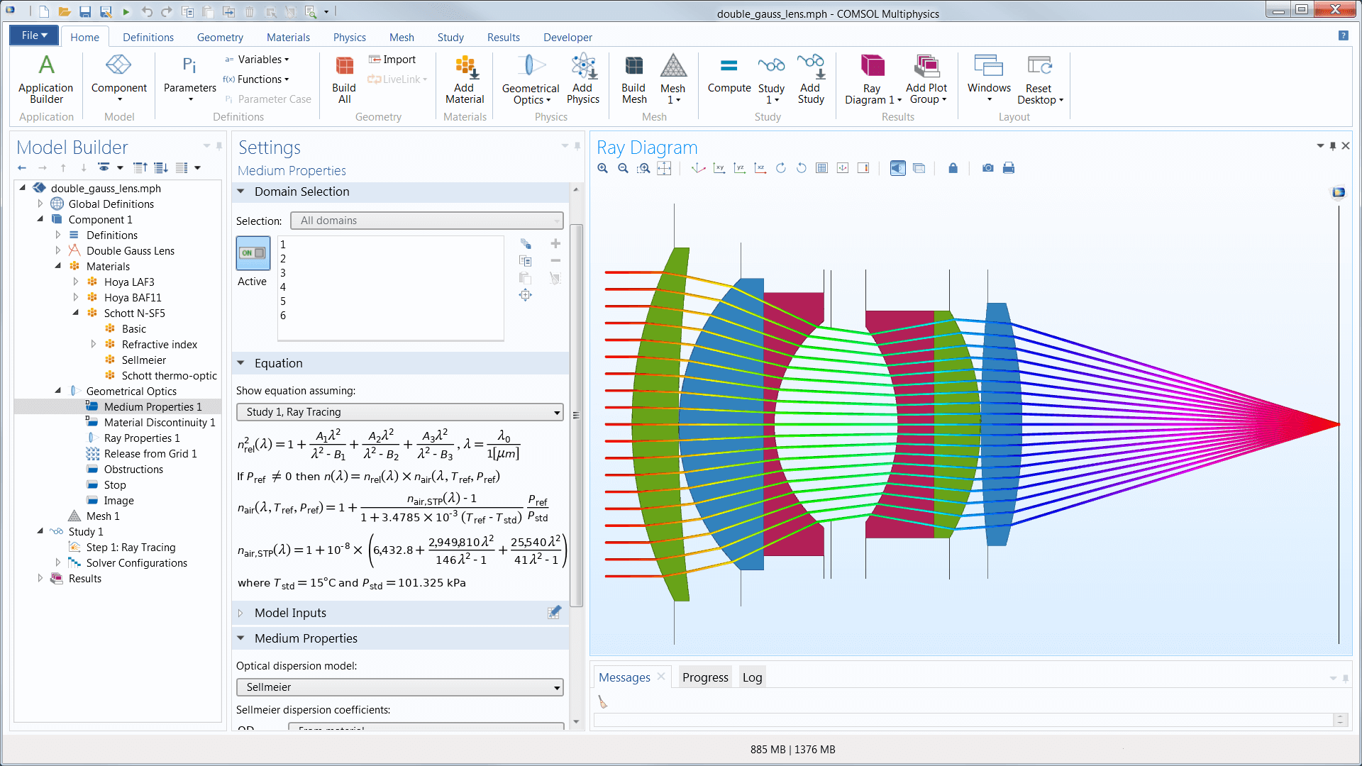
The refractive index of each medium can be specified directly or derived from an optical dispersion relation. The dispersion coefficients, such as Sellmeier coefficients, can be loaded from a material database or entered directly into a user-defined material. The refractive index can be complex, wherein the real part determines the speed of light in the medium, while the imaginary part causes ray attenuation or gain.

Thermo-optic dispersion coefficients are also available to adjust the refractive index based on temperature. There is also a temperature-dependent Sellmeier dispersion model that combines the temperature and wavelength dependence into a single set of Sellmeier coefficients, which is especially useful for cryogenic materials.
Rays automatically detect geometry boundaries in their path without the need to specify the order of ray-boundary interactions. When a ray reaches a surface, it can be diffusely or specularly reflected, refracted, or absorbed. You can also assign conditional boundary interactions or randomly choose between two different boundary interactions with a given probability.

At boundaries between dielectric media, each incident ray is deterministically split into reflected and refracted rays. Total internal reflection is also detected automatically. If the ray intensity is solved for, it is automatically updated for the reflected and refracted rays according to the Fresnel equations. You can also define thin dielectric layers on material discontinuities, which can be used as filters, antireflective coatings, or dielectric mirrors.
The Ray Optics Module includes boundary conditions for
  • Absorption
  • Diffraction gratings
  • Diffuse (Lambertian) scattering
  • Predefined optical components
    • Linear polarizers
    • Linear wave retarders
    • Circular wave retarders
    • Depolarizers
    • User-defined Mueller matrices
  • Reflection/refraction at boundaries between dielectric media
    • Automatically detect total internal reflection (TIR)
    • Reinitialize ray intensity using the Fresnel equations
    • Add single-layer or multilayer thin dielectric coatings to any surface
  • Specular reflection
Rays can be initialized by entering their coordinates directly, importing the coordinates from a text file, or releasing rays from selected geometric entities. Rays can be released from any selection of domains, boundaries, edges, or points in the geometry. There are also dedicated features to produce solar radiation at a specified location on Earth's surface or to release reflected or refracted rays from an illuminated boundary.

When solving for the ray intensity, it can be initialized either by using an expression or loading a photometric data file (specifically an IES file) into the model.

At each release position, the rays can be launched in a user-specified direction, or a number of different directions can be sampled from a spherical, hemispherical, conical, or Lambertian distribution.
The rays can propagate through both homogeneous and graded-index (GRIN) media. They can also be monochromatic or polychromatic, where you can specify a distribution of wavelengths or enter a set of discrete values.

To solve for additional quantities along the ray paths, the Geometrical Optics interface includes built-in handling of ray intensity and polarization. The intensity calculation uses a form of Stokes–Mueller calculus that makes it easy to keep track of fully polarized, unpolarized, and partially polarized rays.
With the COMSOL Multiphysics® postprocessing tools, you have the ability to create both visually pleasing and informative simulation results. You can plot rays as lines, tubes, points, and vectors in 2D or 3D, and color the rays by an arbitrary expression that can vary between different rays and even along each ray's path. When solving for ray intensity, you can also plot polarization ellipses along the rays.

COMSOL Multiphysics® also provides the flexibility to show more than just ray paths, with other dedicated plots to view interference fringes and to decompose optical path difference into individual monochromatic aberration terms. You can also plot the intersection points of rays with a plane, sphere, hemisphere, or a more specialized surface.

After building a ray optics model, there are a host of further opportunities available with the Application Builder that further simplify the simulation workflow. For instance, you can restrict the inputs and control the outputs of your model, parameterize the model geometry, and provide templated report generation.

You can use simulation applications to run your own tests more quickly or distribute applications to other members of your team to run their own tests, further freeing up your time and resources for other projects.

The process is simple:

  1. Transform your ray optics model into a simple user interface (an application)
  2. Customize the application to your needs by selecting inputs and outputs for the application users
  3. Use the COMSOL Server™ or COMSOL Compiler™ products to make them accessible to other team members
  4. Enable your team to run their own design analyses without further assistance

Expand the capabilities of simulation throughout your team, organization, classroom, or customer base by building and using simulation applications.
Optical Design and Diagnostics for the Real World

Optical systems can be extremely sensitive to changes in their environment, especially when operating under extreme conditions such as underwater and outer space. You can create high-fidelity optical simulations using the COMSOL Multiphysics® software and the specialised add-on Ray Optics Module.

The most obvious environmental factor is temperature, since the refractive indices of most materials follow some form of thermo-optic dispersion relation. Physical deformations in the optical system, either due to thermal stress or other applied loads, can also significantly affect the image quality. You can conveniently account for all of these multiphysics phenomena in a single integrated modelling environment, making it easy to conduct coupled structural-thermal-optical performance (STOP) analyses. You can also combine the Ray Optics Module with other add-on modules that offer expanded structural and thermal modelling capability — for example, to account for thermal radiation, conjugate heat transfer, hyperelastic materials, and piezoelectricity.

Every business and every simulation need is different.

In order to fully evaluate whether or not the COMSOL Multiphysics® software will meet your requirements, you need to contact us. By talking to one of our sales representatives, you will get personalised recommendations and fully documented examples to help you get the most out of your evaluation and guide you to choose the best license option to suit your needs.

Fill in your contact details and any specific comments or questions, and submit. You will receive a response from a sales representative within one business day.

Request a Software Demonstration:
Request Software Demonstration

Want to know more?

I Want To Know More Form
(COMSOL®, COMSOL Multiphysics®, Capture the Concept, COMSOL Desktop®) are registered trademarks of COMSOL AB, LiveLink™ is an unregistered trademark of COMSOL AB, ACIS and SAT are registered trademarks of Spatial Corporation. AutoCAD, AutoCAD Inventor and Inventor are registered trademarks or trademarks of Autodesk, Inc., and/or its subsidiaries and/or affiliates in the USA and/or other countries. CATIA is a registered trademark of Dassault Systèmes or its subsidiaries in the US and/or other countries. Microsoft, Excel and Windows are registered trademarks or trademarks of Microsoft Corporation in the United States and/or other countries. Parasolid and Solid Edge are trademarks or registered trademarks of Siemens Product Lifecycle Management Software Inc. or its subsidiaries in the United States and in other countries. SolidWorks is a registered trademark of Dassault Systèmes SolidWorks Corporation. Creo and Pro/ENGINEER are trademarks or registered trademarks of PTC Inc. or its subsidiaries in the U.S. and in other countries. MATLAB is a registered trademark of The MathWorks, Inc. Amazon Web Services, the “Powered by Amazon Web Services” logo, Amazon EC2 and Amazon Elastic Compute Cloud are trademarks of Amazon.com, Inc. or its affiliates in the United States and/or other countries. Mac and Macintosh are trademarks of Apple Inc., registered in the U.S. and other countries. Linux is a registered trademark of Linus Torvalds. Red Hat is a registered trademark of Red Hat, Inc. in the U.S. and other countries. Neither COMSOL nor any COMSOL products are affiliated with, endorsed by, sponsored by, or supported by any of these other trademark owners. Other product names, brand names or logos are trademarks or registered trademarks of their respective holders.
chevron-left-circlechevron-right-circle