Electrodeposition Module

Model and Control Electrodeposition Processes with the Electrodeposition Module

 Read more below 

Want to know more?

I Want To Know More Form

Study All the Important Characteristics of Your Electrodeposition Cells

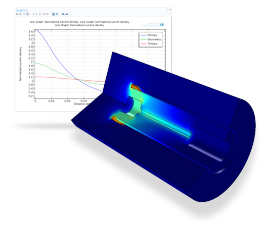
Modelling and simulations are cost-effective methods for understanding, optimising, and controlling electrodeposition processes. A typical simulation yields the current distribution at the surface of the electrodes, and the thickness and composition of the deposited layer. Simulations are used for studying important parameters such as cell geometry, electrolyte composition, electrode reaction kinetics, operating voltages and currents, as well as temperature effects. With information about these parameters, you can optimise the operating conditions of the electrochemical cells and the placement and design of masks, and ensure the quality of your surfaces, while minimising material and energy losses.

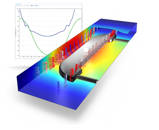
Decorative electroplating assuming secondary current distribution with full Butler-Volmer kinetics for both the anode and the cathode. The deposited thickness on the front and the backside of the piece is shown.
Relevant for an Array of Diverse Electrochemical Applications

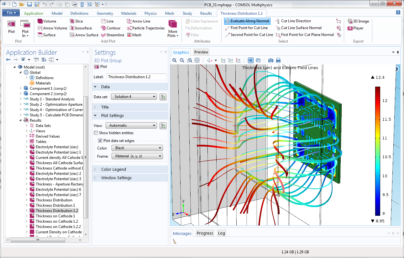
The Electrodeposition Module is suited for a wide variety of applications, including: metal deposition for electronics and electrical parts; corrosion and wear protection; decorative electroplating; electroforming of parts with thin and complex structures; etching; electromachining; electrowinning; and electrorefining. With the Electrodeposition Module, you can consider all of the participating phenomena and simulate them together. More specifically, you may couple the equations that describe current transport and conservation, chemical species transport, charge balances, and electrochemical kinetics. Due to the ability to account for several relevant phenomena, you are able to obtain accurate estimates of the quality, shape, and thickness of the deposit on the surface of the electrodes.

Tools and physics interfaces are available within the Electrodeposition Module for defining the physical characteristics of your process. Predefined formulations allow you to model primary, secondary, and tertiary current distribution effects – often excellent indicators of the surface finish and product quality of your process.

Make Simulation a Part of Your Workflow

As with all chemical processes, you can study many of the effects of your electrodeposition processes at different scales, depending on your purpose. On the microscale level, this could mean investigating the electrochemical kinetics of the participating reactions and the influence of different levellers or striking conditions on the kinetics of electrodeposition. At the counter electrodes, a careful selection of electrocatalyst and electrode micro structure may be required, especially for electrowinning where you need to minimise losses. Simulating these processes and comparing them to experiments or data from your process will allow you to understand the charge transfer reaction mechanism at the electrode surfaces, and derive the electrochemical kinetics parameters, like the exchange current densities and the charge transfer coefficients for each reaction. By knowing these mechanisms and parameters, you can simulate the rate and distribution of deposition or etching at a larger scale. Simultaneously, you will be accounting for the operating conditions of the system, such as cell and electrode geometry, cell voltage or imposed current, masking and shielding, electrolyte composition and flow, gas evolution, and temperature.

The standardised COMSOL Desktop® user interface, which is the basis for the Electrodeposition Module, is also used for all the other add-on products in the COMSOL Product Suite. This enables you to couple the physics describing your electrodeposition or etching process to other modules, such as the Heat Transfer Module for studying thermal effects, or the CFD Module for understanding the effects of two-phase flow. Moreover, other physical characteristics, like structural integrity for example, can be modelled sharing the same model files that you used to model your electrochemical cell. This unified modelling platform is the perfect tool for collaborating with engineers working on the same process across different fields.

Easy-to-use Tools for Modelling Electrodeposition and Electroplating cells

The Electrodeposition Module comes with a number of easy-to-use tools for many of the characteristics associated with electrodeposition and electroplating cells. These include the following:
Electrochemical Reaction Kinetics
Fluid Flow
Electrodeposited Layers
Current Balances in the Electrolyte and Electrodes
Material Transport
Heat Transfer
You can define electrochemical charge transfer reactions where the kinetics expressions can be arbitrary functions of the modelled variables. Examples of these include chemical species concentration, local electrode and electrolyte potential at the electrode-electrolyte interface, and temperature. In the Secondary and Tertiary Current Distribution interfaces, you can also enter parameters for the electrode kinetics, such as exchange current density, anodic and cathodic charge transfer coefficients, stoichiometry, and equilibrium potential for the electrode reactions in your system. Predefined expressions are also available for Butler-Volmer and Tafel expressions. Moreover, you may add several competing reactions on a single electrode surface, for instance add hydrogen evolution at the plating electrode. In the case of tertiary current distribution, you can couple the electrode reactions to the local concentration of the electroactive species in the electrode kinetics expressions by using the variables for the concentration. Concentration overpotential may also be estimated by using Nernst equations for the contribution of the concentration overpotential.
Interfaces for modelling laminar and porous media flow are also available in the Electrodeposition Module, through Navier-Stokes, Darcy's Law, and the Brinkman equations. Turbulent and two-phase flow may be considered by coupling appropriate physics interfaces from the CFD Module to your simulations.
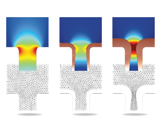
The Electrodeposition Module is further equipped with support for including the effects of geometric changes to the electrochemical process by modelling moving boundaries as the deposited layer grows in thickness at the cathode. Receding or growing surfaces can significantly affect the operation of your cell, and the Electrodeposition Module dynamically considers these changes as part of your simulation. In addition, for the cases where the deposited metal layer or anode thickness variations are small, you can also select a physics interface that keeps track of the plated layer thickness, and how this may influence ohmic effects in the electrode, without actually changing the geometry. Instead, a variable for the thickness is introduced that also affects the local electrical conductance of the electrode. The changes in thickness of the electrode can be automatically calculated from the electrode kinetic expressions by defining the stoichiometry coefficients, the molar mass, and the density of the deposited or consumed metal for the electrode reactions.
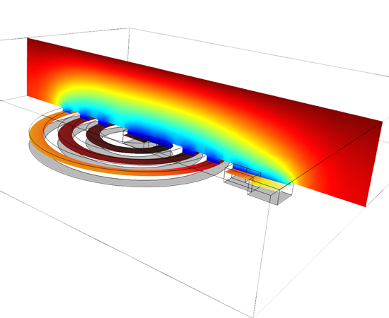
The descriptions of ion transport in the electrolyte and the electron conduction in the electrodes, in combination with the conservation of current and charge, form the backbone of the Electrodeposition Module. In the Primary and Secondary Current Distribution interfaces, ion transport in the electrolyte is assumed to take place through migration of ions, neglecting the influence of diffusion. This is useful when mixing in the electrolyte is good enough to nearly eliminate concentration gradients. Secondary current distribution formulations may also be used when you only have concentration gradients close to the electrode surface, by using analytical expressions for the concentration variations across the boundary layer at the electrode surface. In the Tertiary Current Distribution interfaces, the transport of ions in the electrolyte is described using diffusion, convection, and migration (Nernst-Planck equations). The current density is automatically evaluated by the module through adding all contributions from the transport of ions to the current density. Thus, the current density is described by diffusion and migration of ions, which is required when substantial concentration variations are present in the electrolyte. The current balance in the electrodes is fully coupled to the current balance in the electrolyte at the electrode surfaces through the electrode reaction kinetics. Ohm's law describes the conduction of current in the electrodes. The Electrodeposition Module also contains an interface for modelling current transfer through thin metallic structures or shells, for example to model the strike in the beginning of the plating process. This allows you to model thin electrodeposited layers on non-conductive structures together with current balances in the electrolyte accounting for ohmic losses in the electrodes.
The Electrodeposition Module models the transport of chemical species through diffusion, convection, and migration in dilute and concentrated solutions. The module includes a predefined Nernst-Planck Equations interface, but migration is also added by the module to the Chemical Species Transport interfaces in dilute and concentrated solution, as well as in porous media.
Convection, conduction, and Joule heating can all be modelled when you have the Electrodeposition Module, which contains a specific physics interface for heat transfer through porous media. The module adds contributions from electrochemical processes to the heat balance. For example, it adds the losses due to activation overpotential as heat sources at the electrode boundaries.

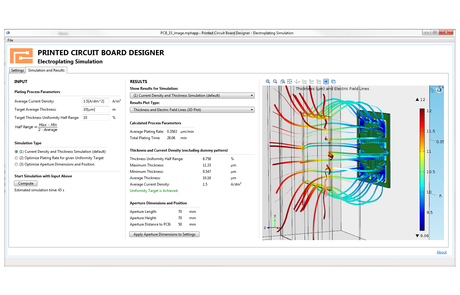
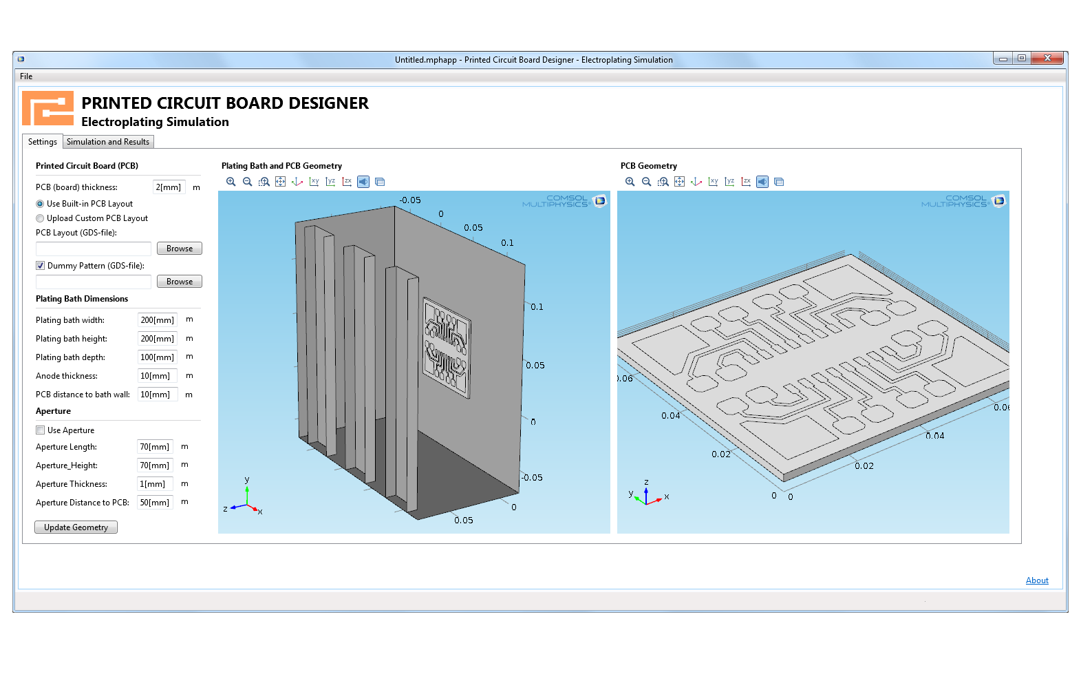
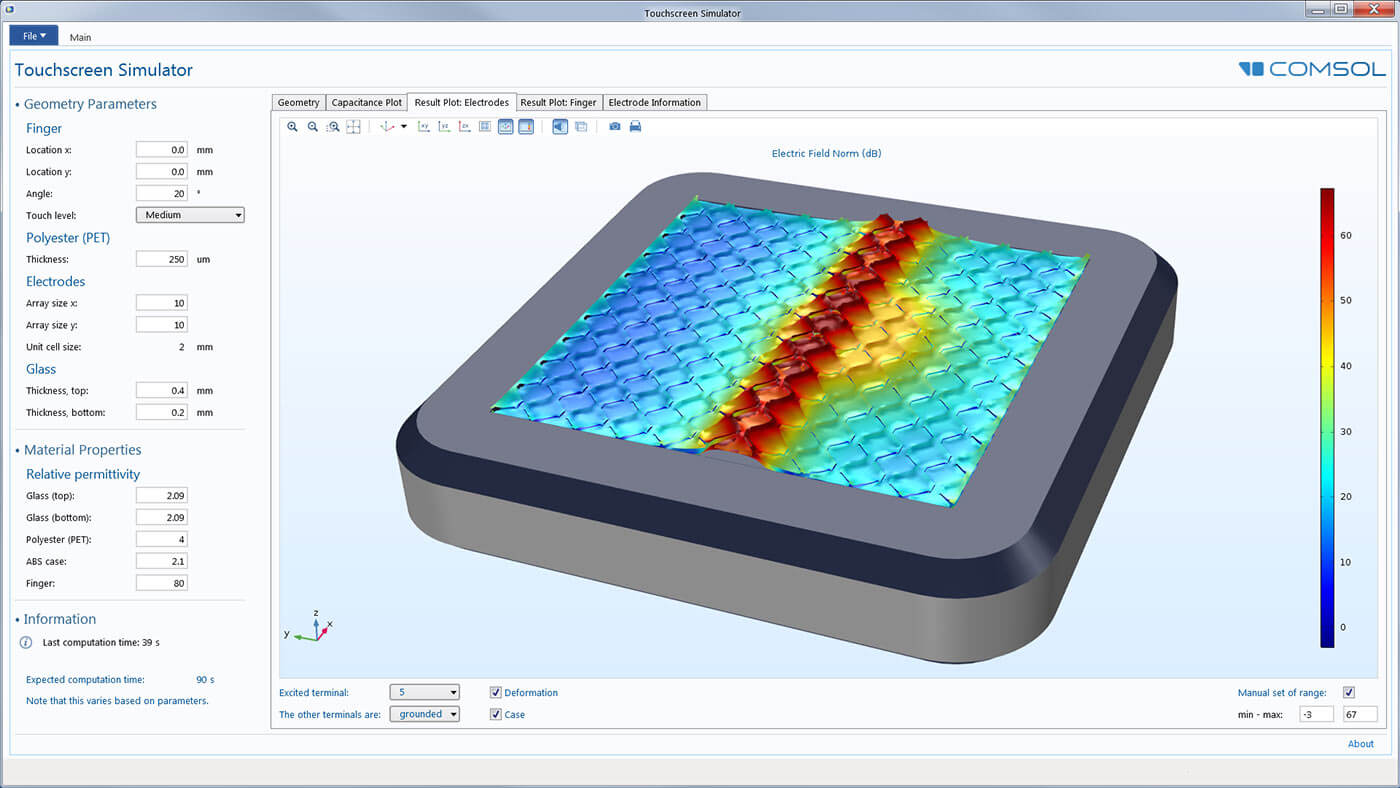
Make your simulation process more efficient with the built-in Application Builder by turning your models into specialised applications with customised inputs and outputs. You can distribute the applications you make to colleagues without simulation expertise so they can perform repetitive analyses on their own, streamlining the design process.

The workflow is simple:

  1. Transform your EM model into a specialised user interface (an application)
  2. Customise the app to your needs by selecting inputs and outputs for the application's users
  3. Add optional code for user-interface logic or additional nonstandard operations
  4. Use the COMSOL Server™ or COMSOL Compiler™ products to make them accessible to other team members
  5. Enable your team to run their own design analyses without further assistance

You can expand the capabilities of simulation throughout your team, organisation, classroom, or customer/vendor base by building and using simulation apps.
If you use the MATLAB® software, you can easily drive COMSOL Multiphysics® simulations with MATLAB® scripts and functions. The LiveLink™ for MATLAB® interfacing product enables you to access COMSOL® operations through MATLAB® commands and blend these commands with your existing MATLAB® code, directly within the MATLAB® environment.

In order to make it easy for you to analyse electromagnetic properties of CAD models and electronic layouts, COMSOL offers the ECAD Import ModuleCAD Import ModuleDesign Module, and LiveLink™ products for leading CAD systems as part of our product suite. The LiveLink™ products make it possible to keep the parametric CAD model intact in its native environment but still control the geometric dimensions from within the COMSOL Multiphysics® software, as well as produce simultaneous parametric sweeps over several model parameters.

You can also synchronise Microsoft® Excel® spreadsheet data with the parameters you define in the COMSOL Multiphysics® environment via the LiveLink™ for Excel® interfacing product.

Available interfacing products include:
  • LiveLink™ for MATLAB®
  • ECAD Import Module
  • CAD Import Module
  • Design Module
  • LiveLink™ products for leading CAD software
  • LiveLink™ for Excel®

View all available interfacing products in the product suite.
Product Features

  • Primary, Secondary, and Tertiary Current Distribution interfaces for current balances in the electrolyte
  • Formulations for electroneutrality, supporting electrolyte, or Poisson equation for the charge balance equations
  • Nernst-Planck equations in dilute and concentrated solutions
  • Nernst-Einstein equation for relating mobility and diffusivity in electrolytes
  • Ohm's law and conservation of current in the electrodes
  • Nernst equation for equilibrium potential and concentration overpotential
  • Automatically coupled stoichiometry and Faraday's law for automatic coupling of material and current balances to electrode reactions
  • Electrode kinetics accounting for activation and concentration overpotential
  • Electrocatalysis for counter electrodes, for example oxygen evolution
  • Butler-Volmer and Tafel equations for predefined kinetics
  • Electrode thickness variable at electrode surfaces that affects local conductance for small changes in electrode geometry during deposition
  • Nernst-Planck-Poisson Equations
  • Electrophoretic Transport
  • Current distribution based on the boundary element method
  • Moving boundaries for deposited layers on electrodes and electrochemical etching for large changes in electrode geometry
  • Joule heating due to ohmic losses in the electrodes and in the electrolyte
  • Heating due to activation losses
  • Throwing power estimates
  • Wagner Number estimates
Application Areas
  • Anodising
  • Bipolar effect estimation in metal cells
  • Chrome plating
  • Chroming
  • E-coating
  • Electrocoating
  • Electrocoloring
  • Electrodeposition for mining applications
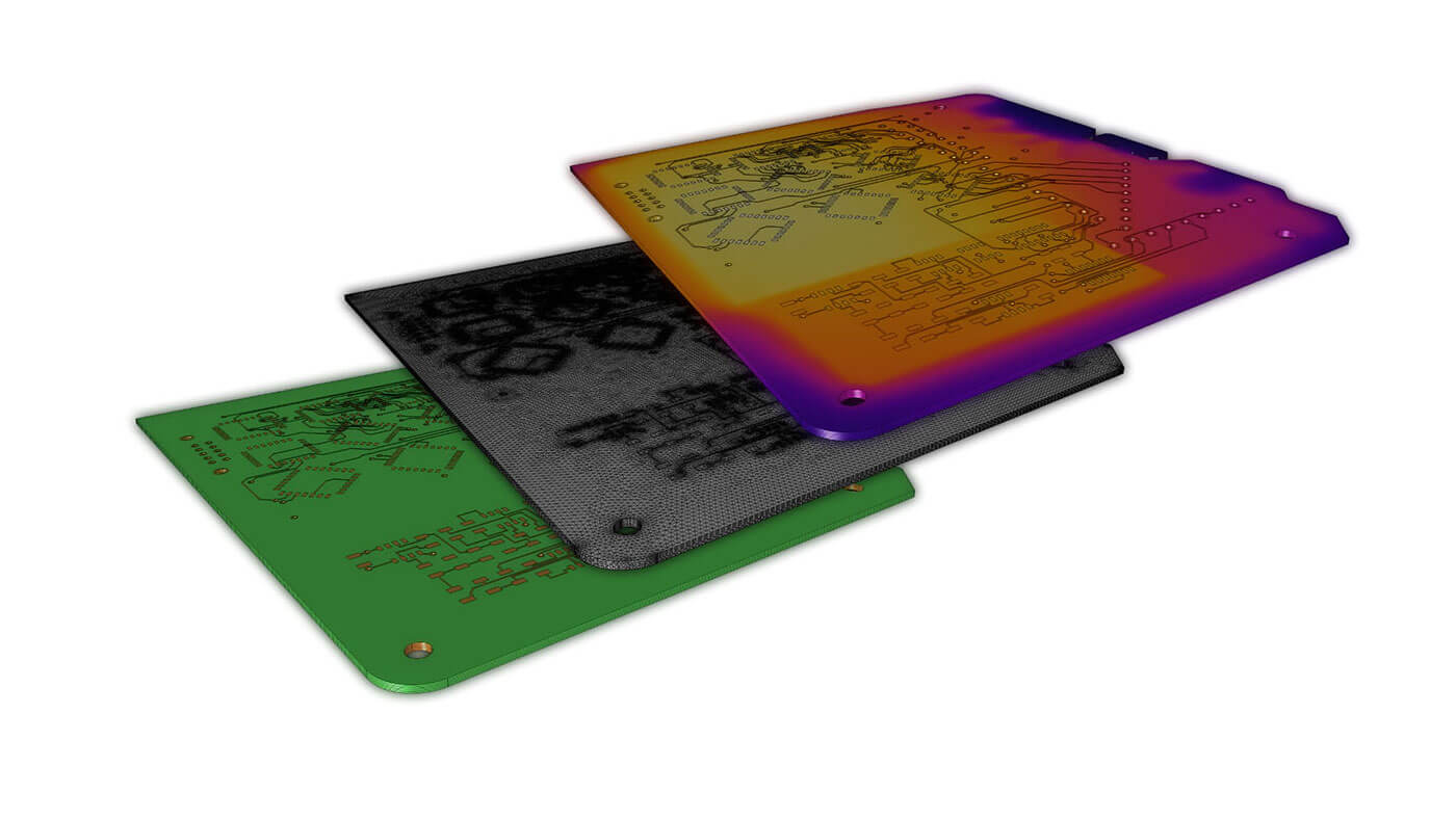
  • Electrodeposition for PCB manufacturing
  • Electroforming
  • Electroplating
  • Electrowinning
  • Etching
  • Flush layer plating
  • Functional electroplating
  • Hull cells
  • Striking methods
  • Surface finishing
  • Wear resistance coatings
  • Electrochemical manufacturing
  • Electrochemical polishing
  • Electrochemical machining
  • Shielding and masking

Every business and every simulation need is different.

In order to fully evaluate whether or not the COMSOL Multiphysics® software will meet your requirements, you need to contact us. By talking to one of our sales representatives, you will get personalised recommendations and fully documented examples to help you get the most out of your evaluation and guide you to choose the best license option to suit your needs.

Fill in your contact details and any specific comments or questions, and submit. You will receive a response from a sales representative within one business day.

Request a Software Demonstration:
Request Software Demonstration

Want to know more?

I Want To Know More Form
(COMSOL®, COMSOL Multiphysics®, Capture the Concept, COMSOL Desktop®) are registered trademarks of COMSOL AB, LiveLink™ is an unregistered trademark of COMSOL AB, ACIS and SAT are registered trademarks of Spatial Corporation. AutoCAD, AutoCAD Inventor and Inventor are registered trademarks or trademarks of Autodesk, Inc., and/or its subsidiaries and/or affiliates in the USA and/or other countries. CATIA is a registered trademark of Dassault Systèmes or its subsidiaries in the US and/or other countries. Microsoft, Excel and Windows are registered trademarks or trademarks of Microsoft Corporation in the United States and/or other countries. Parasolid and Solid Edge are trademarks or registered trademarks of Siemens Product Lifecycle Management Software Inc. or its subsidiaries in the United States and in other countries. SolidWorks is a registered trademark of Dassault Systèmes SolidWorks Corporation. Creo and Pro/ENGINEER are trademarks or registered trademarks of PTC Inc. or its subsidiaries in the U.S. and in other countries. MATLAB is a registered trademark of The MathWorks, Inc. Amazon Web Services, the “Powered by Amazon Web Services” logo, Amazon EC2 and Amazon Elastic Compute Cloud are trademarks of Amazon.com, Inc. or its affiliates in the United States and/or other countries. Mac and Macintosh are trademarks of Apple Inc., registered in the U.S. and other countries. Linux is a registered trademark of Linus Torvalds. Red Hat is a registered trademark of Red Hat, Inc. in the U.S. and other countries. Neither COMSOL nor any COMSOL products are affiliated with, endorsed by, sponsored by, or supported by any of these other trademark owners. Other product names, brand names or logos are trademarks or registered trademarks of their respective holders.
chevron-left-circlechevron-right-circle