Pipe Flow Module

Model Transport Phenomena and Acoustics in Pipe Systems with the Pipe Flow Module

 Read more below 

Want to know more?

I Want To Know More Form

Consider All Process Variables with Reduced Computational Resources

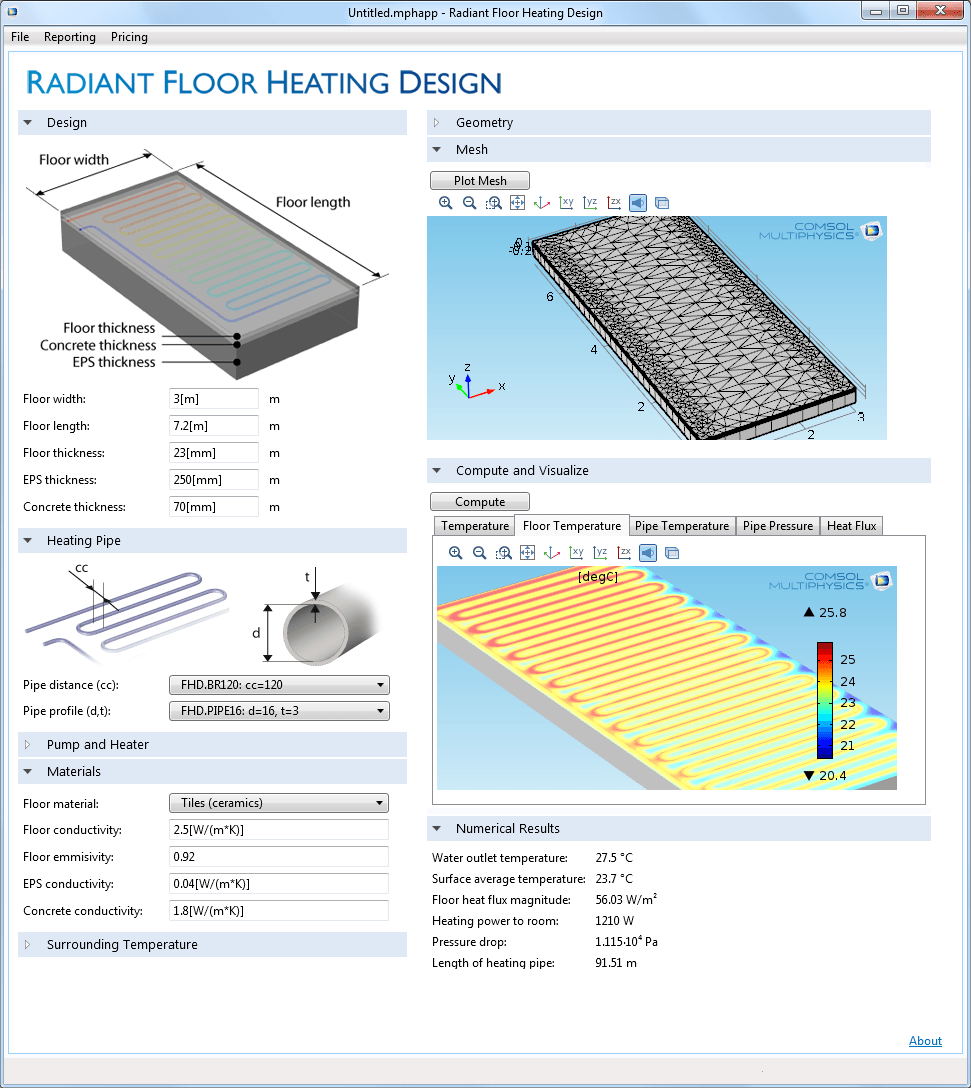
The Pipe Flow Module is used for simulations of fluid flow, heat and mass transfer, hydraulic transients, and acoustics in pipe and channel networks. It can be easily integrated with any of the other modules in the COMSOL® Product Suite for modelling the effects piping has on larger entities, such as cooling pipes in engine blocks or feeding and product channels connected to vessels. This allows for the conservation of computational resources in your overall modelling of processes that consist of piping networks, while still allowing you to consider a full description of your process variables within these networks. Pipe flow simulations provide the velocity, pressure, material concentrations, and temperature distributions along pipes and channels, while it can also simulate acoustic wave propagation and the water hammer effect.

Ideal for Modelling Incompressible Fluid Flow Regimes

The Pipe Flow Module is suitable for modelling incompressible flow in pipes and channels whose lengths are large enough that flow can be considered fully developed. With this assumption it uses edge elements, solving for the tangential cross-section averaged velocity along the edges, to avoid meshing the cross section of the pipe with a full 3D mesh. This means that the modelled variables are averaged in the pipe's cross sections and vary only along the length of the pipe. Built-in expressions for Darcy friction factors cover the entire flow regime including laminar and turbulent flow, Newtonian and non-Newtonian fluids, different cross-sectional shapes or geometries, and a wide range of relative surface roughness values. These can be varied according to their position in the network, or directly related to the variables you are modelling.

Friction is not the only contribution to pressure loss in pipe networks. The Pipe Flow Module also considers the effects of bends, contractions, expansions, T-junctions, and valves that are computed through an extensive library of industry standard loss coefficients, while pumps are also available as flow-inducing devices. As with any physics interface in the COMSOL Product Suite, you can freely manipulate the underlying equations, add your own source or sink terms, and express physical property as functions of any model variable. COMSOL Multiphysics® also allows you to bring in data to describe a certain material property or process parameter, as well as subroutines written in MATLAB®.

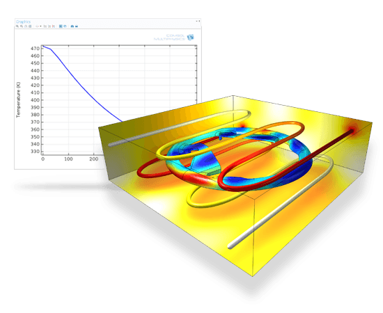
Cooling of a steering wheel injection mold: Non-isothermal pipe flow is fully coupled to the heat transfer simulation of the mold and polyurethane part.
Physics Interfaces for Simulating Pipe Flow

The Pipe Flow Module features a number of physics interfaces for the simulation of pipe flow and processes dependent upon it:
Coupling Pipe Flow to Other Physics and Applications
Physics for Water Hammer Analysis and Pipe Acoustics
Pipe Flow Simulations Great for Many Types of Industries
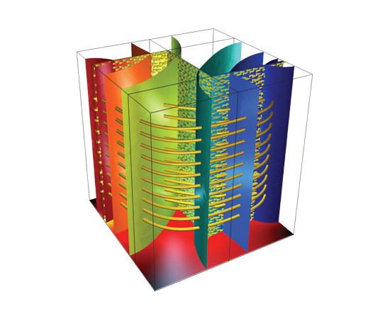
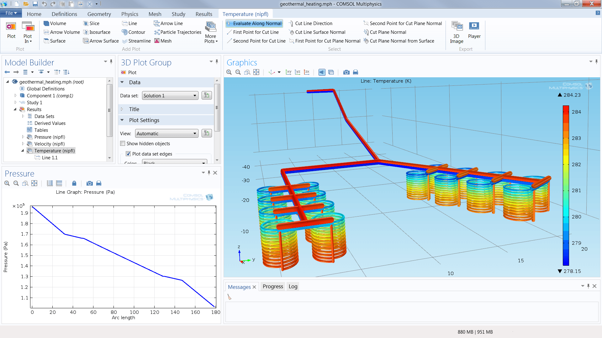
The physics in the Pipe Flow Module describe the conservation of momentum, energy, and mass in the fluids inside a pipe or channel system. These systems can easily be coupled to other systems that cannot be described using the approximative methods in the Pipe Flow Module, but require a full description of the system's physics in 2D or 3D. The Pipe Flow Module allows the mapping of data from edges, to surfaces, and to volumes, and vice versa. This means that the flow or heat transfer in a pipe network can be coupled to that occurring in, for example, a fully-meshed 3D vessel, and solved simultaneously. Furthermore, as with all physics-based products in the COMSOL Product Suite, this coupling can occur between different physics formulations, so that a property like thermal stress can be just as easily solved, for example thermal stresses in an engine block equipped with cooling channels.

The Pipe Flow Module features specific tailor-made physics interfaces for modelling heat and mass transfer and chemical reactions. The pipe network can be embedded in, for example, a 3D solid domain. In the case of heat transfer, the module computes the energy balance in your pipe systems including the contributions from the interaction with the 3D domain, which are expressed as sources or sinks in the pipe equations. This is automatically done under the hood by activating the interaction with 2D or 3D solid material in the graphical user interface (GUI), where you can also select from the available correlations for forced and natural convection to the surrounding environment, pipe materials, and pipe wall thicknesses that are included with the Pipe Flow Module. The material transport-based physics interfaces solve a mass balance within the pipe system and, while being coupled to the description of the pipe flow, also consider diffusion, convection, dispersion, and chemical reactions.
The Pipe Flow Module models compressible flow brought about by rapid hydraulic transients, through taking the elastic properties of both the fluid and high wall into account. These effects can occur through the rapid closing of the valve, and are known as the water hammer effect.

The propagation of acoustic waves along flexible pipes is also a contributing factor to the design, planning, and building of these networks. When combined with the Acoustics Module, the Pipe Flow Module is able to perform acoustics analyses in both the frequency and time domains. Once again, the physics that are solved for in the Pipe Flow Module can be seamlessly coupled to any other physics within the pipe network, and any physics in the system surrounding the network.
The Pipe Flow Module is appropriate for modelling all types of pipe and channel networks where flow, mass and heat transfer, and acoustic waves travel. This includes the piping systems of chemical and process industry plants, power stations, refineries, petroleum and water in pipelines, ventilation systems, and cooling systems in engines and turbines. Furthermore, it is a great addition to the modelling that you perform using COMSOL Multiphysics and its suite of add-on products. This includes optimising intricate and integrated cooling systems in turbines, moulds, casts and heat exchangers, planning ventilation systems in buildings, and designing geothermal heating systems.
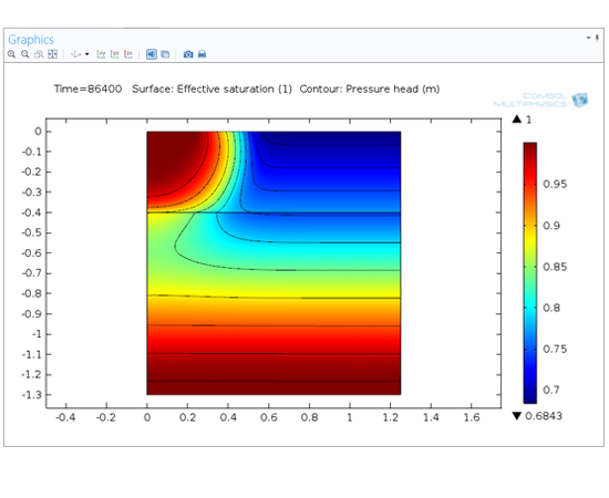
Heat transfer occurs through conduction, convection, and dispersion, and must take into account the different conductivities that occur between the solid and fluid phases. In many cases, the solid phase can be made up of differing materials with different conductivities, and there can also be a number of differing fluids. Mixing rules are provided for calculating the effective heat transfer properties in the Heat Transfer in Porous Media interface. This also contains expressions for heat dispersion due to the nature of the porous media, as well as a term for the background geothermal heating. Dispersion is caused by the tortuous path of the liquid in the porous medium, which would not be described if only the mean convective term was taken into account.

Compaction and subsidence modeling is enabled by a very powerful physics interface for poroelasticity. The Poroelasticity interface combines a transient formulation of Darcy’s law to a linear elastic solid mechanics of the porous media matrix. The poroelasticity coupling means that the fluid flow affects the compressibility of the porous medium, while changes in volumetric strains will in turn affect the momentum, material, and heat transport. This interface includes an expression of the stress tensor, as a function of the strain tensor and the Biot-Willis coefficient.

Product Features

  • Laminar and turbulent flow in pipes and channel networks
  • Darcy friction factors for all flow regimes, different cross-sectional geometries, and for different surface roughness
  • Extensive library of industry standard loss coefficients for bends, contractions, expansions, T-junctions, and valves
  • Flow-inducing coefficients for pumps
  • Nonisothermal flow coupled to heat transfer for all flow regimes
  • Heat transfer within pipe flow and to the surrounding environment, including conduction through pipe walls, solids, and free and forced convection in the surrounding volume
  • Newtonian and non-Newtonian fluids
  • Material transport through diffusion, dispersion, convection, and chemical reaction
  • Reacting Flow that couples material transport directly to pipe flow
  • Water Hammer effects caused by rapid hydraulic transients in pipe networks
  • Pipe acoustics in the frequency and time domains*


* Requires the Acoustics Module.

Application Areas

  • Chemical process simulations
  • Chemical reactions in pipes
  • Cooling systems
  • Geothermal systems
  • Heat exchangers and cooling flanges
  • Heat transfer in pipes
  • Hydraulics
  • Lubrication
  • Mass transfer in pipes
  • Nonisothermal pipe flow
  • Oil refinery pipe systems
  • Pipe acoustics
  • Pipe flow
  • Pipe networks in chemical plants
  • Water and oil pipelines
  • Water hammer equations


Every business and every simulation need is different.

In order to fully evaluate whether or not the COMSOL Multiphysics® software will meet your requirements, you need to contact us. By talking to one of our sales representatives, you will get personalised recommendations and fully documented examples to help you get the most out of your evaluation and guide you to choose the best license option to suit your needs.

Fill in your contact details and any specific comments or questions, and submit. You will receive a response from a sales representative within one business day.

Request a Software Demonstration:
Request Software Demonstration

Want to know more?

I Want To Know More Form
(COMSOL®, COMSOL Multiphysics®, Capture the Concept, COMSOL Desktop®) are registered trademarks of COMSOL AB, LiveLink™ is an unregistered trademark of COMSOL AB, ACIS and SAT are registered trademarks of Spatial Corporation. AutoCAD, AutoCAD Inventor and Inventor are registered trademarks or trademarks of Autodesk, Inc., and/or its subsidiaries and/or affiliates in the USA and/or other countries. CATIA is a registered trademark of Dassault Systèmes or its subsidiaries in the US and/or other countries. Microsoft, Excel and Windows are registered trademarks or trademarks of Microsoft Corporation in the United States and/or other countries. Parasolid and Solid Edge are trademarks or registered trademarks of Siemens Product Lifecycle Management Software Inc. or its subsidiaries in the United States and in other countries. SolidWorks is a registered trademark of Dassault Systèmes SolidWorks Corporation. Creo and Pro/ENGINEER are trademarks or registered trademarks of PTC Inc. or its subsidiaries in the U.S. and in other countries. MATLAB is a registered trademark of The MathWorks, Inc. Amazon Web Services, the “Powered by Amazon Web Services” logo, Amazon EC2 and Amazon Elastic Compute Cloud are trademarks of Amazon.com, Inc. or its affiliates in the United States and/or other countries. Mac and Macintosh are trademarks of Apple Inc., registered in the U.S. and other countries. Linux is a registered trademark of Linus Torvalds. Red Hat is a registered trademark of Red Hat, Inc. in the U.S. and other countries. Neither COMSOL nor any COMSOL products are affiliated with, endorsed by, sponsored by, or supported by any of these other trademark owners. Other product names, brand names or logos are trademarks or registered trademarks of their respective holders.
chevron-left-circlechevron-right-circle